How should a pneumatic shield box handle feed-throughs, filtering, and grounding?
Configure feed-throughs separately for RF, power, and data, then verify shielding, transmission, and grounding for each. One filtering approach cannot serve every port: an SMA pass-through, a USB 3.2 line at 20 Gbps, and a DC power feed have completely different requirements. Filtering has to match the signal band, protocol bandwidth, voltage and current, and the delivered mechanical structure. A photograph of a cable route is not evidence that the interface meets a shielding figure.
Key points
- Separate feed-through design for RF, power, and data paths
- Filter selection driven by band, protocol bandwidth, voltage, and current
- High-speed data needs a dedicated filter panel, not a generic feed-through
- Grounding continuity verified on the assembled unit
- Interface capability confirmed by test, never inferred from a photograph
Products this applies to
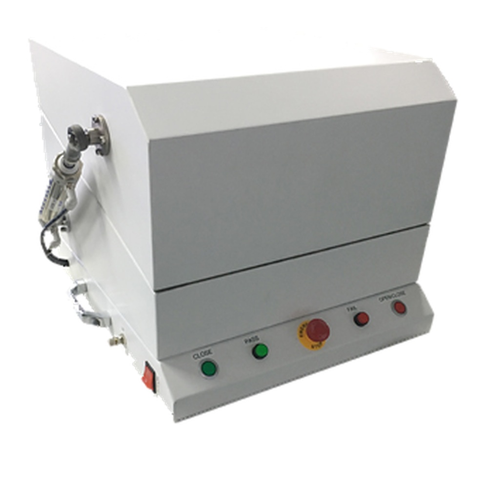
Pneumatic Shield Box, Top Opening
A benchtop RF shielded enclosure with a side-mounted pneumatic cylinder driving a top-opening lid, f…
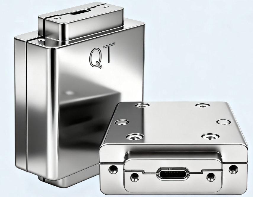
USB 3.2 Gen 2×2 Type-C Filter Panel
A Type-C filter feed-through for shield rooms and enclosures, passing USB 3.2 Gen 2×2 at 20 Gbps and…
Discuss this configuration
Send the device details and the measurement you need to make. We will confirm which specifications are fixed and which need verification on your sample.
Contact engineering