SPDT RF Switch, TTL/USB Controlled
0.1–8 GHz, over 70 dB isolation to 3 GHz
Overview
Two-path switching is the most common requirement in a test fixture: test antenna A or antenna B, or route the signal to the instrument or to a load. A solid-state SPDT does it without the wear and contact resistance drift of a mechanical relay.
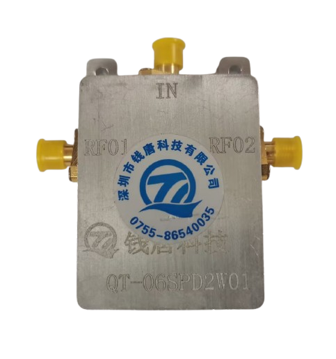
The unit covers 0.1–8 GHz with 50 Ω SMA-female ports. Insertion loss is under 1 dB and isolation above 70 dB from 0.1–3 GHz; above 3 GHz the figures are under 3 dB and above 50 dB respectively. VSWR is 1.20 maximum up to 3 GHz and 1.40 maximum to 8 GHz.
Control is DC 5 V over Type-C with AT commands (AT+RF0, AT+RF1), returning OK. Switching is under 1 ms, continuous wave power handling is 1 W, and the body measures approximately 60 × 40 × 10 mm. The −55 to +85 °C extended option is available alongside the standard −25 to +65 °C range.
Specifications
Features
- Solid-state switching avoids relay wear and contact resistance drift
- Over 70 dB isolation up to 3 GHz for sensitive measurements
- AT command control over USB Type-C, easy to script
- Under 1 ms switching fits inside a test cycle
- Extended temperature option down to −55 °C and up to +85 °C
Typical applications
- Fixture path selection
- Antenna A/B switching
- Instrument routing with a load path
Discuss this configuration
Send the device details and the measurement you need to make. We will confirm which specifications are fixed and which need verification on your sample.
Contact engineering