SP4T RF Switch, USB Controlled
One input to four outputs, 0.7–8 GHz, AT command control
Overview
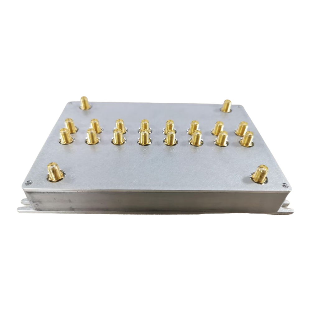
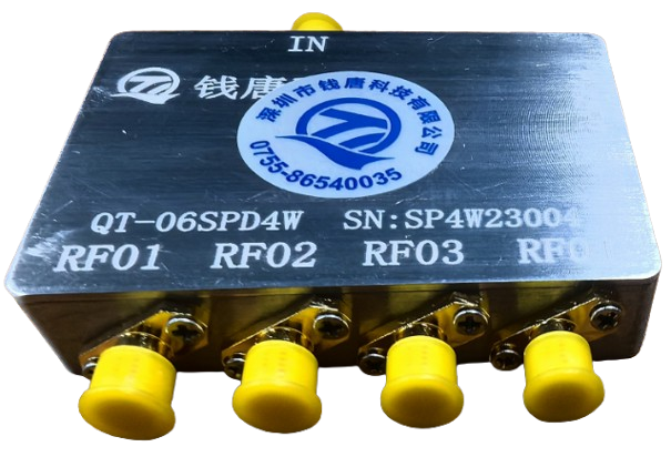
One instrument port and four test paths is a common requirement in a shield box station: you want to reach four antennas or four fixtures without re-cabling. This switch does that electrically, so the change happens inside a test sequence rather than at the bench.
The main specification covers 0.7–8 GHz at 50 Ω with SMA female connectors. Control is DC 5 V over Type-C, and AT commands (AT+RF0 through AT+RF3) select channels 1 to 4. Switching time is specified below 1 ms.
One caveat worth stating plainly: the datasheet has minor inconsistencies around the low-frequency boundary and insertion loss at the 8 GHz endpoint. Segment-level performance should be confirmed against a full test report before you design a link budget around the upper band.
Specifications
Features
- Routes one instrument port to four paths without re-cabling
- AT command control over USB Type-C, easy to script
- Sub-millisecond switching keeps path changes inside the test cycle
- Compact metal housing for bench or in-fixture mounting
Typical applications
- Shield box multi-antenna stations
- Coupling fixture path selection
- Lab signal routing
Discuss this configuration
Send the device details and the measurement you need to make. We will confirm which specifications are fixed and which need verification on your sample.
Contact engineering