Programmable Attenuator, 4×4, 0.6–6 GHz
Four inputs, four outputs, 0–110 dB with Ethernet control
Overview
Simulating a changing RF path in a lab usually means chaining fixed attenuators and switches. A programmable unit replaces that with four independent channels that can be set from software, which is what makes repeatable path-loss scenarios practical.
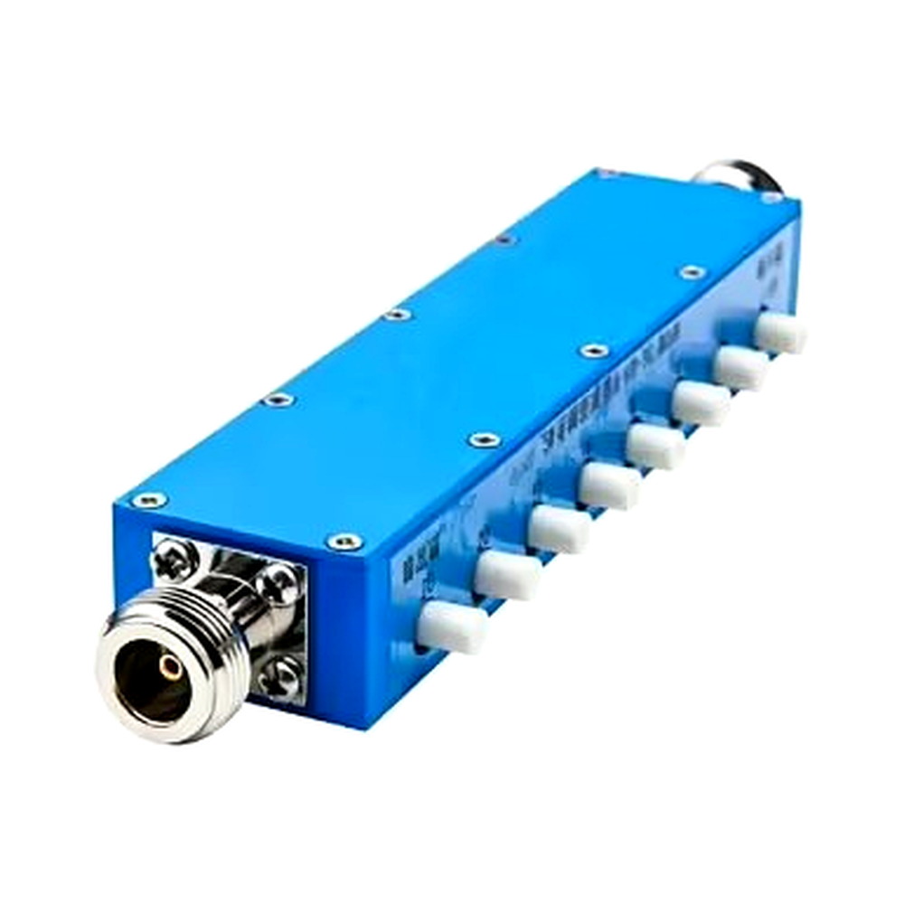
The platform provides four inputs and four outputs, covering 0.6–6 GHz with 0–110 dB attenuation and a choice of 0.5 dB or 1 dB steps. Typical use is between an RRU, a UE, and test instruments, where path loss has to follow a defined profile rather than a fixed value.
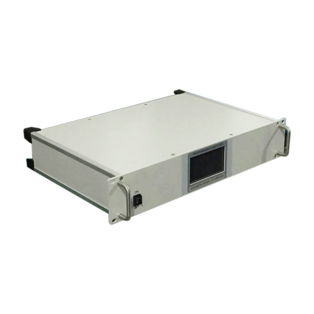
Control is over Ethernet for remote automation, with a front touchscreen for local operation. Channel count, step size, and control protocol are confirmed per project.
Specifications
Features
- Four independent channels replace a chain of fixed attenuators and switches
- Ethernet control supports scripted attenuation profiles
- Front touchscreen for local setup without a PC
- Covers 0.6–6 GHz with up to 110 dB range
- Selectable 0.5 dB or 1 dB step size
Typical applications
- RRU and UE path-loss simulation
- Receiver sensitivity testing
- Automated RF scenario testing
Discuss this configuration
Send the device details and the measurement you need to make. We will confirm which specifications are fixed and which need verification on your sample.
Contact engineering